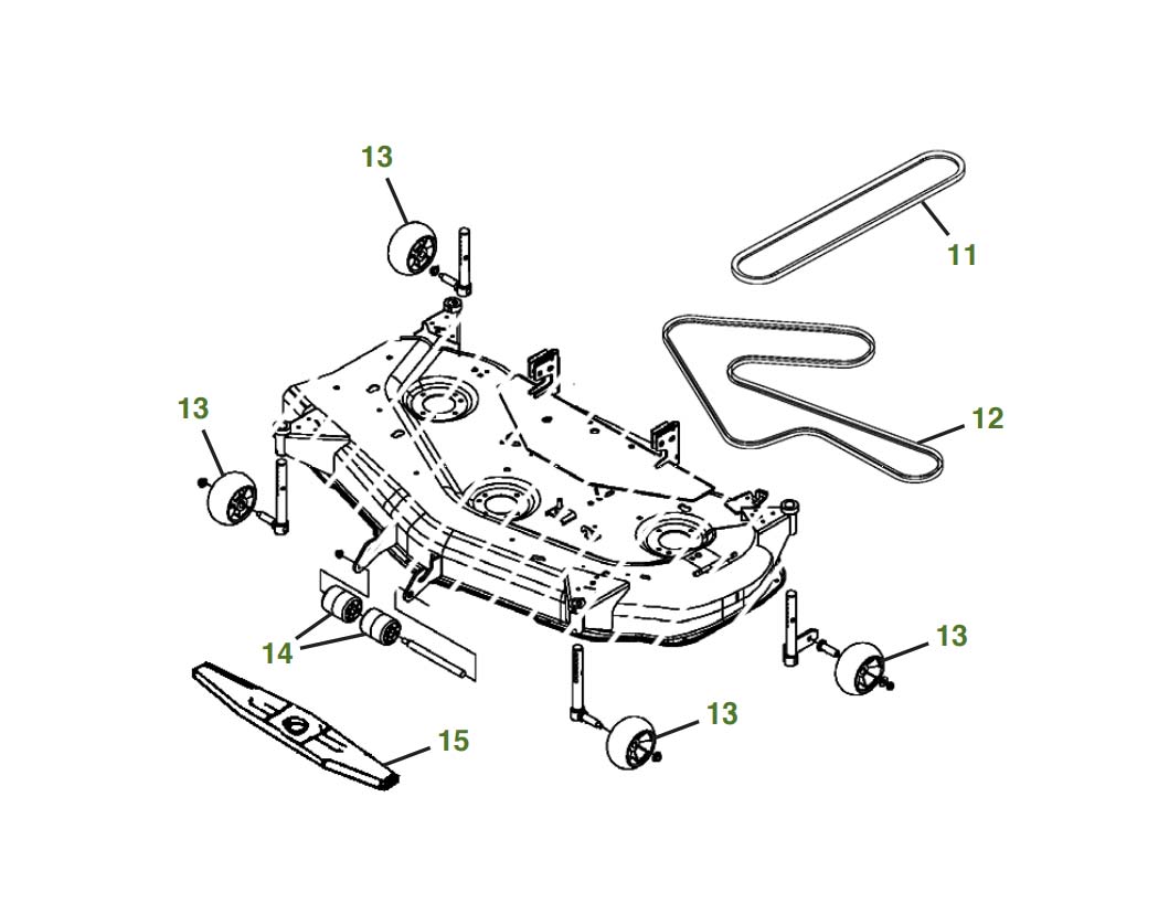
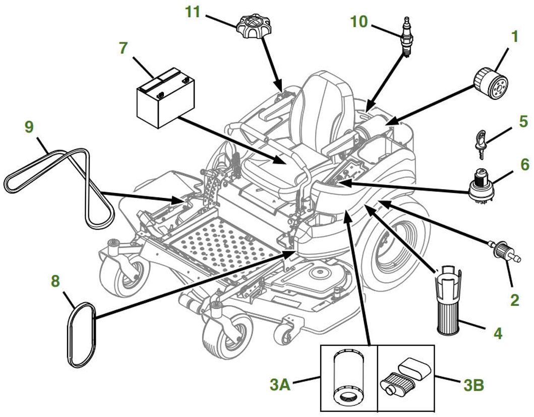
John Deere 737 zero turn parts diagram deck parts diagram is your guide to understanding the intricate workings of this powerful lawn mowing machine. Whether you’re a seasoned mechanic or a DIY enthusiast, deciphering the parts diagram is essential for successful maintenance and repairs.
The deck, the heart of the zero-turn mower, is responsible for cutting the grass, and its components work in unison to deliver a smooth and efficient cut.
This comprehensive guide will take you through the intricacies of the John Deere 737 zero-turn mower deck, providing a detailed explanation of its parts and their functions. You’ll learn how to interpret the parts diagram, identify specific components, and troubleshoot common deck problems.
We’ll also explore the importance of proper maintenance and safety precautions when working with this powerful machine.
Introduction to the John Deere 737 Zero-Turn Mower
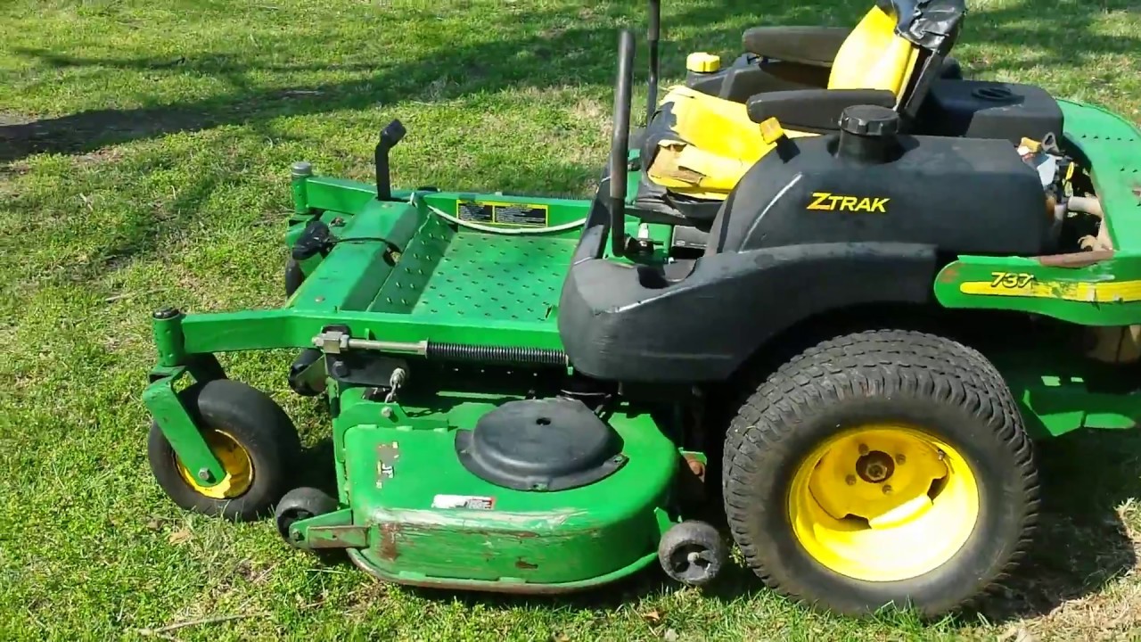
The John Deere 737 zero-turn mower is a popular choice for homeowners and landscapers seeking a powerful and maneuverable mowing solution. This model is known for its cutting efficiency, durability, and user-friendly features. Understanding the parts diagram for the John Deere 737 is crucial for ensuring proper maintenance and timely repairs.
Key Features and Specifications
The John Deere 737 zero-turn mower boasts a range of features that contribute to its performance and ease of use. Here are some key highlights:
- Powerful Engine: The 737 typically utilizes a Briggs & Stratton or Kawasaki engine, providing ample power for efficient mowing.
- Zero-Turn Maneuverability: The zero-turn design allows for precise control and tight turns, making it ideal for navigating around obstacles and achieving a clean cut.
- Cutting Deck Options: The 737 comes with a variety of deck sizes, ranging from 48 inches to 54 inches, to suit different mowing needs.
- Adjustable Cutting Height: The cutting height can be easily adjusted to achieve the desired lawn length.
- Durable Construction: The 737 is built with high-quality materials, ensuring long-lasting performance and resistance to wear and tear.
Importance of Understanding the Parts Diagram
The parts diagram serves as a visual guide to the components and their locations within the John Deere
737. Understanding the parts diagram is essential for the following reasons
- Identifying Parts:The diagram clearly labels each component, making it easy to identify specific parts needed for maintenance or repairs.
- Ordering Replacement Parts:When ordering replacement parts, the diagram helps ensure that you order the correct part number.
- Troubleshooting Issues:By understanding the relationships between different parts, you can better troubleshoot potential problems and identify the source of the issue.
- Performing Maintenance:The parts diagram provides a visual reference for regular maintenance tasks, such as changing blades, checking fluids, and inspecting components.
Deck Parts Diagram Overview
The deck is the heart of any zero-turn mower, responsible for cutting the grass. Understanding its components and how they work together is crucial for maintaining and troubleshooting your John Deere 737.
Deck Components
The deck comprises several essential parts that work in unison to achieve a clean and efficient cut.
- Blades:The blades are the primary cutting tools, rotating at high speed to chop grass. They are typically made of high-quality steel and come in various sizes and designs depending on the mowing application.
- Spindle Assemblies:Spindle assemblies house the blades and bearings, providing a stable and durable mounting point for the blades. They also contain a drive system, often powered by a belt, to rotate the blades.
- Deck Shell:The deck shell is the structural base of the deck, providing support for the blades, spindles, and other components. It is typically made of durable steel and designed to withstand the rigors of mowing.
Deck Operation, John deere 737 zero turn parts diagram deck parts diagram
The deck operates by drawing grass into the cutting area, where the blades chop it into fine clippings. The deck shell directs the airflow, ensuring that the clippings are evenly distributed and discharged.
Understanding the Parts Diagram
Parts diagrams are essential tools for understanding the components of your John Deere 737 zero-turn mower and identifying the parts you need to repair or replace. These diagrams visually represent the machine’s assembly, showing the location and relationships of individual components.
Types of Parts Diagrams
Parts diagrams for the John Deere 737 are available in various formats, each offering unique advantages:
- Printed Parts Catalogs:These traditional catalogs provide comprehensive diagrams for all parts of the mower, often with detailed descriptions and part numbers. They are a valuable resource for experienced mechanics and those who prefer a physical reference.
- Online Parts Catalogs:John Deere offers online parts catalogs that provide interactive diagrams and part information. These catalogs allow you to search for specific parts by model number, description, or part number, making it easier to find what you need.
- Service Manuals:John Deere service manuals include detailed parts diagrams and exploded views of the mower, often with step-by-step instructions for repair and maintenance procedures. These manuals are essential for professional technicians and serious DIY enthusiasts.
Reading and Interpreting Parts Diagrams
Parts diagrams use standardized symbols and conventions to represent the different components of the mower. Understanding these conventions is crucial for accurately identifying parts.
- Part Numbers:Each part in the diagram is assigned a unique part number. This number is used to order the part from John Deere or an authorized dealer.
- Exploded Views:Many parts diagrams use exploded views, which show the components disassembled and spread out, revealing the relationships between parts. This helps you visualize how the machine is assembled and identify parts that may be hidden in a fully assembled machine.
Just like understanding the intricate workings of a John Deere 737 zero turn mower’s deck parts requires a detailed diagram, comprehending the electrical flow of a 2012 Smart Car Fortwo’s front end necessitates a visual representation. The 2012 Smart Car Fortwo front end electrical diagram offers a clear roadmap for troubleshooting any electrical issues, much like the John Deere 737 zero turn parts diagram guides you through potential maintenance needs.
- Color Coding:Some diagrams use color coding to differentiate between different types of parts, such as engine parts, deck parts, and transmission parts. This can help you quickly locate the parts you need.
Using the Diagram to Identify Parts
Let’s consider an example. Suppose you need to replace the drive belt on your John Deere 737. You can use the parts diagram to locate the belt and identify its part number.
- Locate the Belt:Find the diagram for the drive system of your mower. The belt will be shown as a continuous line connecting the engine pulley to the transmission pulley.
- Identify the Part Number:Look for the part number associated with the drive belt. This number will be printed on the diagram or listed in a table accompanying the diagram.
- Order the Part:Use the part number to order the correct drive belt from John Deere or an authorized dealer.
Key Deck Parts and Their Functions
The deck of a John Deere 737 zero-turn mower is responsible for cutting the grass. It houses the blades, spindles, and belts that work together to provide a clean and efficient cut. Understanding the function of each part is essential for proper maintenance and troubleshooting.
Deck Parts and Functions
The following table lists key deck parts and their functions:
| Part Name | Part Number | Description | Function |
|---|---|---|---|
| Blade | Various | Sharp, rotating metal component | Cuts the grass. The blade’s sharpness and shape determine the quality of the cut. |
| Spindle | Various | Rotating shaft that supports the blade | Provides a stable platform for the blade to rotate and ensures proper blade height. |
| Belt | Various | Rubber band that transmits power from the engine to the spindles | Transfers power from the engine to the spindles, allowing the blades to rotate. |
| Deck Shell | Various | Metal housing that encloses the deck components | Protects the deck components and directs airflow for optimal cutting performance. |
Maintenance and Repair Using the Parts Diagram

The John Deere 737 zero-turn mower parts diagram is an essential tool for any owner who wants to perform maintenance or repairs on their machine. It provides a detailed visual representation of every component, making it easy to identify and locate parts.
The parts diagram is also helpful for understanding the relationship between different components and how they work together. This knowledge is crucial for diagnosing and troubleshooting problems, as well as for performing preventative maintenance.
Common Maintenance Tasks Requiring the Parts Diagram
The parts diagram is a valuable resource for many common maintenance tasks, including:
- Replacing blades:The diagram clearly shows the blade mounting system, allowing you to easily identify the correct blade type and size for your mower. It also shows the location of the blade bolts and nuts, making it easy to remove and replace the blades.
- Changing the oil:The diagram indicates the location of the oil drain plug and fill cap, ensuring you drain and refill the oil correctly.
- Replacing air filters:The parts diagram shows the location of the air filter housing and the type of filter required for your mower.
- Checking and adjusting the belt tension:The diagram shows the location of the belt tensioner and the correct belt tension specifications for your mower.
- Inspecting and cleaning the deck:The parts diagram highlights the components of the mowing deck, including the spindles, blades, and deck housing. This helps you identify any potential problems and clean the deck effectively.
Troubleshooting Common Issues
The parts diagram is a powerful tool for diagnosing and troubleshooting common issues with your John Deere 737 zero-turn mower. It can help you identify the source of the problem and determine the appropriate solution. Here are some examples:
- Mower not starting:If your mower won’t start, the parts diagram can help you check the ignition system, fuel system, and battery connections. It shows the location of components like the spark plugs, fuel lines, and battery terminals, allowing you to inspect and troubleshoot them systematically.
- Mower cutting unevenly:If your mower is cutting unevenly, the parts diagram can help you identify the cause. It shows the location of the blades, spindles, and deck housing, allowing you to check for damage or wear and tear. It also shows the adjustment points for the deck height, allowing you to make necessary adjustments to ensure even cutting.
- Mower making strange noises:If your mower is making unusual noises, the parts diagram can help you pinpoint the source of the problem. It shows the location of the engine, transmission, and other moving parts, allowing you to identify any potential issues. For example, if you hear a rattling noise, the diagram can help you determine if it’s coming from the engine, the deck, or the wheels.
Importance of Proper Deck Maintenance

Regular maintenance of your John Deere 737 zero-turn mower’s deck is essential for optimal performance, extended lifespan, and a clean, even cut. Neglecting maintenance can lead to problems like uneven cutting, reduced efficiency, and premature wear and tear on components.
Benefits of Regular Deck Maintenance
Proper maintenance ensures that your deck is operating at its peak performance, resulting in a variety of benefits.
- Improved Cutting Quality:A well-maintained deck will deliver a clean, even cut, leaving your lawn looking its best.
- Enhanced Efficiency:Regular maintenance ensures optimal blade sharpness and proper deck height, resulting in efficient cutting and reduced strain on the engine.
- Extended Deck Lifespan:By addressing potential issues early on, you can prevent major problems and extend the life of your deck.
- Reduced Repair Costs:Routine maintenance helps prevent costly repairs by catching minor issues before they escalate.
- Improved Safety:A well-maintained deck operates smoothly and safely, reducing the risk of accidents or injuries.
Maintaining the Deck According to Manufacturer Recommendations
To ensure optimal performance and longevity of your John Deere 737 zero-turn mower deck, follow these recommendations from the manufacturer:
- Inspect the Deck Regularly:Check for any signs of damage, wear, or debris buildup. Pay close attention to the blades, spindles, and belts.
- Clean the Deck:Remove grass clippings, dirt, and other debris regularly to prevent rust and corrosion.
- Sharpen the Blades:Dull blades can result in uneven cutting, scalping, and increased stress on the engine. Sharpen them according to the manufacturer’s specifications.
- Lubricate Moving Parts:Regularly lubricate the spindles, bearings, and other moving parts to prevent wear and tear. Refer to the owner’s manual for recommended lubricants.
- Check Belt Tension:Ensure that the drive belts are properly tensioned to prevent slippage and premature wear.
- Replace Worn Parts:Replace worn or damaged parts promptly to avoid further damage and ensure optimal performance.
Tips for Using the Parts Diagram Effectively: John Deere 737 Zero Turn Parts Diagram Deck Parts Diagram

The John Deere 737 Zero-Turn Mower parts diagram is a valuable tool for understanding the mower’s components and facilitating maintenance and repair. It’s essential to learn how to navigate and interpret the diagram to maximize its usefulness. Here are some practical tips to help you effectively use the parts diagram.
Understanding the Diagram’s Structure
The parts diagram typically presents a visual representation of the mower, broken down into various sections. Each section focuses on a specific assembly, such as the deck, engine, or transmission. The diagram will usually include:
- Part Numbers:Each part is assigned a unique number for easy identification and ordering.
- Part Names:A description of each part is provided to clarify its function.
- Exploded View:The parts are shown in a disassembled state, allowing you to visualize their arrangement and relationships.
- Assembly Instructions:Some diagrams may include instructions on how to assemble or disassemble certain components.
Finding Specific Parts Quickly
To locate a specific part, use the following steps:
- Identify the Section:Determine the section of the mower that contains the part you need. For example, if you need a blade, look for the deck section.
- Use the Index:Most diagrams have an index that lists all the parts with their corresponding numbers. Use this index to quickly find the part you’re looking for.
- Follow the Part Number:Once you’ve identified the part number, locate it on the diagram. The part number will be associated with the corresponding part in the exploded view.
Interpreting the Diagram’s Information
The parts diagram provides essential information about the mower’s components. To interpret this information correctly, consider these points:
- Part Numbers:These are crucial for ordering replacement parts. Ensure you use the correct part number to avoid ordering incompatible parts.
- Part Names:The names provide a clear description of each part’s function. This helps you understand the purpose of each component.
- Exploded View:The exploded view shows the relationship between different parts and how they fit together. This is valuable for understanding the assembly process.
- Assembly Instructions:If included, these instructions can help you assemble or disassemble components correctly. Follow them carefully to avoid damage or improper assembly.
Answers to Common Questions
Where can I find a John Deere 737 zero-turn parts diagram?
You can find parts diagrams on the official John Deere website, authorized dealer websites, and online parts retailers. Always ensure you are using a reputable source for accurate information.
What is the purpose of the deck on a zero-turn mower?
The deck is the cutting mechanism of the zero-turn mower. It houses the blades, spindles, and other components that work together to cut the grass.
How often should I maintain the deck on my John Deere 737?
Regular maintenance is crucial for optimal performance and longevity. Refer to your owner’s manual for specific recommendations, but generally, you should inspect and clean the deck after each use, sharpen the blades regularly, and lubricate moving parts as needed.